|
Fixed Bias Protection
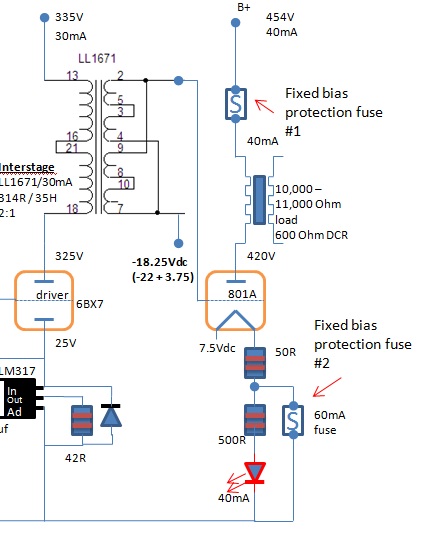
Fixed bias protection: For those that use fixed bias for their power stage, it would be detrimental if the bias run away. It could damage the power tube, burn the output transformer + power transformer (ouch!) and even fry your beloved speakers if the OPT primary and secondary windings are shorted due to current overload. There could be many causes to bias run away. The most common ones are failure of DC bias supply, weakening of power tube, connection wire breaks and etc. Our aim here is to protect the whole system! One of the methods is strategic fuse placement for protection. We can place fuses into the power stage itself. There are 2 positions where the fuse could be used: position #1 and position #2. We shall talk about the pros and cons of these 2 positions using the 801A class A2 amplifier design we discussed previously.
Position #1: fuse place between B+ and output transformer If bias runaway happens, current increases and blows the fuse. It works all right at first glance, but… If you analyze further, there are hidden problems with this fixed bias protection method. Once tube ran away, the power tube is cut from the power supply due to fuse blow. Due to the under-loading effect on the power supply after the power tube is removed from the circuit due to fuse blow, the B+ might rise up higher than the intended voltage and stress the driver stage, stress the PSU capacitors and power capacitors, especially those marginal circuits with very marginal or close to maximum limit components. So, this is not very safe after all. Use this fixed bias protection at our own risk if you know your amplifier design! Position #2: fuse placed at power tube cathode When we place fuse at the cathode, things changed drastically. What you can see from the circuit above is that under normal conditions, the 500R resistor in series with LED is transparent in the circuit due to the 60mA fuse providing the short circuit path to ground as it is with the least resistance. When fuse blows due to over-current, the 500R resistor and LED are no longer transparent and will be in series with the tube cathode. Current will flow through the resistor and LED and turn it to a cathode bias circuit to bring back the runaway bias. Due to the potential developed at the cathode, the more negative bias will bring the bias back and limit the current flow. Current will be limited by the 500R resistor. The lighting of LED will indicate that a runaway has happened, which is another plus point for this circuit. When LED lights, you know there is a problem! Install the LED at the front panel or top plate so that it is visible to you. Note that a 0.5W high power LED can be used at this position that takes up to 100mA current max. Ordinary LED does not apply here since they can only take up to 20mA current max. Another thing to note is that your filament DC supply (if is direct heated) must not be grounded for this circuit to work. This fixed bias protection circuit is highly recommended over #1. Install it with confidence and have peace of mind that your HIFI system is well protected! Return from DIY Audio Guide / Tips and Tricks / Fixed Bias Protection to DIY Audio Guide
|


