|
801A Tube
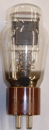
I can’t help but talk more about the 210, 10, 10Y, 801A tube or VT-62. In the previous article, we talk about the history, 801A output transformers,and the general characteristics. In this page, let’s look at the electrical characteristics and applications in depth. 801A Vacuum Tube Characteristics. 7/27/2011: 801A amplifier - class A2 design.
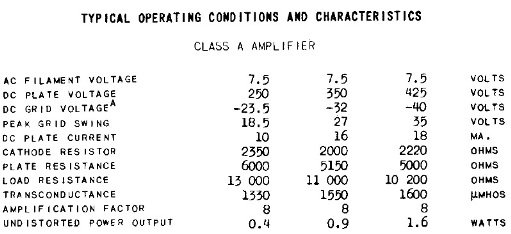
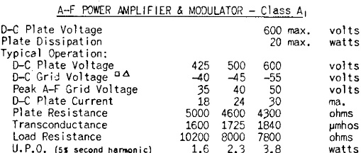
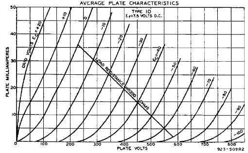
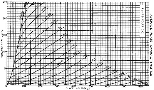
Electrical Characteristics Let’s look at the difference between the 10 and 801A tube. The 801A is a totally different beast compared to the 10. The 801A can generate >2x the power of 10 in class A operation. The maximum B+ for 801A went up to 600V instead of 425V that 10 can handle. On the other hand, 801A is made to be able to handle class A2 operation, and boost up the power by ~2x again. Do not look down on 10 though. From experience, 0.4W – 1.6W is decent output power if coupled with the right, high efficiency speakers. The 0.7W from 1626 has proven to be very satisfactory, if not decent for many audiophiles or tube-o-philes. Did I mention that 1626 can go into class A2 operation as well? I could not find the original datasheet for 10Y. If you have one, please kindly share it with me, highly appreciated! Class A2 operation / load line The 1st graph is for tube 10. A 10K load resistance line has been drawn. Do notice that the tube 10 has the capability to slightly go into class A2 operation to about +20V on the grids. If you’re using tube 10 as integrated amplifier or power amplifier, give it a very good driver capable of supplying lots of current and voltage swing. It will surprise you with additional power you drive it really hard.
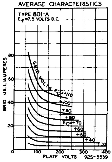
The 2nd graph is for tube 801A. Now things start to get interesting. You can see that the graph extends to the left with grid voltage swinging into positive region, up to +100V before it reaches saturation. This enables us to drive it to deep class A2 operation. Choose a load that gives equal headroom to both the positive and negative grid to maximize the output power.
From a brief drawing and measurement I’ve with the average plate characteristics graph, here are the initial operation points I recommend for this tube:
With only loading the 801A up to 90% of maximum dissipation, it will last a long, long time, not to mention the already durable tube it is! If you’ve very high efficiency speakers, load it to 80% and it will last you forever, if your other aspects are design right! Do take note that for class A2 operation, you’ve to either inter-stage couple or direct couple it. RC coupling will not get it to work at class A2 satisfactory. During class A2, the grid will start to draw current as it moves into positive grid voltage, and that current will have to come from either the grid supply or from the driver stage.
Grid current / driver stage design One of the criteria for class A2 is positive grid voltage. The datasheet for 801A tube has such specifications documented. The driver stage will need to supply the current and still maintain the voltage swing and low distortion. With the operating point suggested in previous paragraph, the grid swing will be from -100V to + 45V with the center point at the grid bias of -22V. Therefore, the driver stage will need to supply 145V peak-to-peak and capable of sinking 10mA at least to the grid without breaking a sweat. Ideal case would be to provide more for more headroom and lower distortion. Classic wimpy driver tube does not apply here! We can consider having a small power tube to do the job. For 2 stage designs, one of the ideal candidates would be the Telefunken EC8020, but that’s pretty hard to find! Other alternatives would be the Western Electric 437A or the STC 3A-167M triodes. For the latter two, step-up input transformer will be needed to provide sufficient swing to the drive the 801A tube. For 3 stage design, choices are plenty! 6CK4, 6AH4GT, 6BX7, EL84, 45, 2A3, 10Y, or even 801A tube itself could be used in the driver stage. The one I chose for my upcoming project is the 6BX7. 6BX7 datasheet.There are some creative folks out there that uses solid-stage amplifier as the driver too, like for example the TDA2030 amplifier chip. For me, my philosophy is – why walk when you can fly, why solid-stage when you can vacuum tube? For coupling, go for inter-stage or direct coupling for class A2 requirements. R-C coupling is fine if you just plan to work in class A envelope. Do go for 4:1 or 2:1 step down to provide more juice to the grid of 801A tube. 1:1 is fine too if your driver stage is powerful enough. I’ve researched a few Lundahl inter-stage transformers and found that the LL1671 / 30mA configured to a 2:1 step down ratio could be a good candidate. Check it out! Lundahl LL1671 datasheet.Output / Power Stage Design If you’re aiming for class A2 operation, you cannot use self biasing. Fixed bias is the only way to go for class A2. For those only interested in class A (A1), you can use either one. You can use an adjustable LM317 / LM337 series regulator to supply the negative or positive bias. There is a HVT (high voltage) version available too for those exceeding the standard LM317 / LM337 maximum output voltage. I like the idea of parafeeding the output stage as well as it has excellent bass response. But, getting a decent plate choke will be an issue. If you know of any plate chokes capable of handling 50mA, have inductance of 100H+ and have decent price, please let me know. In addition, getting a good pair of coupling capacitors costs a lot! On top of that, chassis real estate is needed to house the extra pair of chokes and coupling capacitors. So, decide yourself! There is no best solution or design here. All have their pros and cons. Recommended operating points Apart from the recommended operating points in the 10 & 801A datasheet, and also the one I just recommended, here are some other points that is used by others and could act as a good reference for the readers here:
Filament supply design For filament supply, DC is unavoidable! With 7.5V and 1.25A on the filament, hum is quite inevitable with conventional AC heating on high efficiency speakers. Here are several options to consider:
Do not forget to apply soft start to the filament to protect the precious 10 / 801A tube. Soft Start.I’ll go into the filament supplies in detail in other pages. Alright, that’s all for now. Coming up next would be the actual 801A tube amplifier design article itself! Ken 7/14/2011 Return from DIY Audio Guide / Electronics Components / 801A Tube to DIY Audio Guide
|
