|
Hybrid Amplifier, 5687, TA2022
5687 – TA2022 hybrid amplifier – vacuum tubes meet solid state devices, match made in heaven! In auto world, we have the hybrid cars to save on fuel consumption and save the mother earth (other than money! :P )! In audio world, we have the same thing too. The purposes, one is to save mother earth, the other is to have the best of both worlds, tube warmth and solid state power (low energy consumption!). This hybrid amplifier would be very suitable for those looking for tube warmth and power to drive their medium to low efficiency speakers since not all people are blessed with speakers that are over 92dB/w/m efficiency. For those with high efficiency speakers, congratulations, it sounds even better. That’s the nice thing about Tripath Class T amplifier. In this page, we’re going to play with a tube preamp + class T amplifier from Tripath. For this project, I chose the Tripath TA2022 class T amplifier chip to match with a 5687 tube preamplifier using tube rectifier EZ81. So, this is a hybrid of tube preamplifier stage with a solid state power amplifier stage. Check out the details of the above mentioned components here: Tripath TA2022 evaluation board
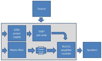
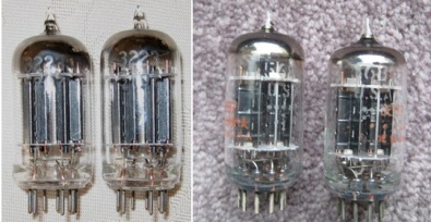
Above is the block diagram of the hybrid amplifier. It uses a tube preamplifier coupled with a TA2022 class T amplifier. The tube preamplifier uses EZ81 choke loaded tube rectified power supply. The TA2022 amplifier uses a EI transformer for the power supply. A mains filter is connected to the TA2022 power transformer to clean up the noise to and from the TA2022 amplifier, shielding the noises getting to the 5687 preamplifier stage. 5687 double triode has been one of my favorite tubes! I’ve a stash of Tung-sol 5687-WA (military version) residing in my storeroom. The sound of Tung-sol 5687-WA is warm, detailed and powerful. I had compared it with the General Electric 5-star 5687 and I still prefer the Tung-sol 5687-WA although the GE 5-star 5687 does have its’ strengths too. 5687 triode is a powerful tube as a preamp or in driver stage. Quite a number of people used it as a power tube too, to generate output power of around 0.7 Watt. This is already powerful enough if one has very high efficiency speakers or has lower demand on the playback volume.
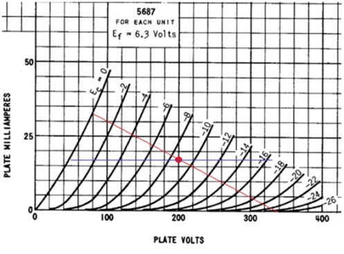
5687 used in this hybrid amplifier is a twin triode, meaning that there are 2 triodes inside a single 5687 tube. 5687 tube is quite versatile too, being able to accept 6.3V or 12.6V filament supply. This gives me wider selection of power transformers out in the market. Also, with a heater center tap, I can easily elevate the filament voltage to a higher Vdc to reduce hum and filament noise. This has always been some of the thing I must implement whenever I build tube amplifiers. I like to bias the 5687 at about ~3.5W per triode. The maximum both triodes can handle is 7.5W and each unit can have plate dissipation of up to 4.2W with the 1st condition not exceeded. The operating point that I find optimum and I like the best is:
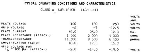
This gives the most headroom for the tube to swing positively and negatively equally without exceeding the maximum plate voltage (note the red dot on the 5687 I/V curve). The Tung-sol 5687 datasheet listed out 3 typical operating conditions that we can try out too in this hybrid amplifier. If you happen to try them, do let me know how does it sound and compare it to the sound of the operating point I chose in my hybrid amplifier. Many thanks in advance!
For preamplifier stage in the hybrid amplifier, I chose the common cathode topology for the simplest yet one of the best sounding circuits available. The parts count is low. Therefore, one can really have the best components used in the circuit without being worried that the cost would exceed the budget allocated. Even with such simple design, there are lots of customization and tweak-ability to the circuit. Let me just list some of them here:
Each of these will present a different presentation to the sound. Choose your own poison!
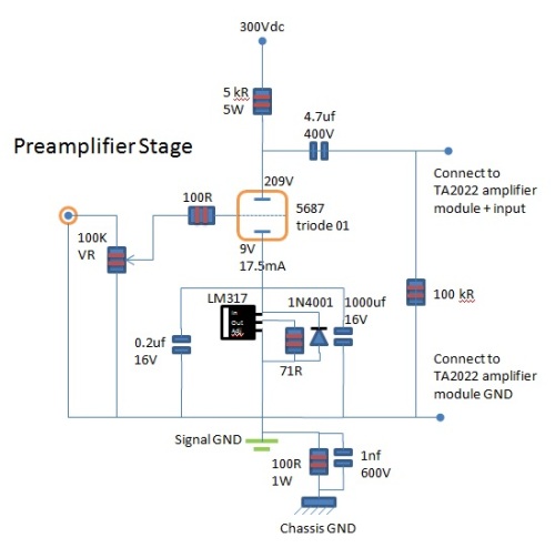
Above is the design I would do if I were to build the hybrid amplifier again. The difference between this and the one I built is on the cathode biasing. The original used a 500 Ohm resistor on the cathode and this version uses a constant current source to draw 17.5 mA constantly from the 5687 tube. The circuit with constant current source will have much better linearity. The formula for setting the current for LM317 would be 1.25 divided by the resistor value. For example in this case, 1.25 divided by 71 Ohm would be around 17.5 mA. Iccs = 1.25 / R Do take note that for ordinary LM317T, the maximum input-output voltage differential is 40Vdc. If the cathode bias is more than that, please use the LM317HVT that can withstand up to 60Vdc. In this case, it is more than enough. If you look at the 5687 plate I/V curve again, you will see 2 lines, red is the operating point for normal resistor cathode bias where as blue is being the constant current source using LM317 configured as constant current source. If you take a closer look at the red line, you would have noticed that at higher plate voltage and more negative biasing, the distance between the curves shortens. This signifies that the voltage change at grid is no longer linear. This introduces distortion to the output waveforms. For constant current operation, the blue line possesses equal distance for all the operating points, i.e. lower distortion.
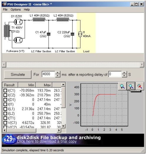
For the 5687 preamplifier power supply, what tool is more useful than the Duncan PSU Designer II? I want to take this opportunity to thank Duncan for creating such a wonderful tool to the DIYers worldwide. Plugging in the EZ81 with full-wave choke-input rectification, the end result for the B+ is 300Vdc. The above power supply is shared between left and right channel. Two 40H chokes are used to reduce the power supply ripple to an inaudible level since the Tripath TA2022 module is quite high in gain and every little noise is amplified. If you look closely on the B+ voltage graph, you can see that the B+ voltage never surge higher than the intended steady state 300Vdc level. The power supply is design in such a way for 2 reasons – longevity and sound. Overshoot will stress or even damage the components in the amplifier. Overshoot also means ringing and oscillations – this is bad for the preamplifier. The smooth steep ramp signifies a solid power supply design that equals to good sound! Do insert a RC filter per channel close to each plate to improve the channel separation and reduce crosstalk. A film capacitor and a low (~100 Ohm) value resistor (take note on the wattage) will be fine. The total current consumption for the 5687 tube is 35mA and I add another 5mA for the power supply drain resistor to improve regulation and discharge the capacitors when the amplifier is switched off. Connect a drain resistor across the power supply capacitor positive and negative terminals. The rating should be 5W 100 kR. This helps to prolong the life of the amplifier and avoid shock hazard since capacitors can keep the charge for a very long time. Enough with the 5687 preamplifier stage, let’s move to the power stage in the hybrid amplifier. To simplify the project, I chose module instead of building a TA2022 amplifier from scratch. For this project, I selected the TA2022 module from Connexelectronic. There are other TA2022 modules that you can choose from too. Just go to eBay or Google for it.
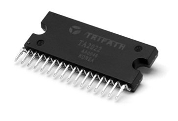
This is the heart of the TA2022 amplifier module used in the hybrid amplifier. This is a fully integrated amplifier with internal FETs for the amplification. The output could be bridged to produce more power if required too.
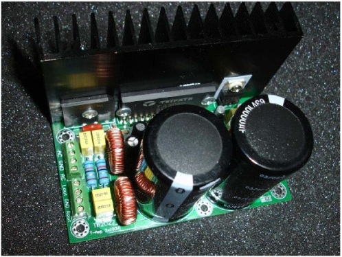
This TA2022 amplifier module employed in this hybrid amplifier is quite easy to use. Just connect a power transformer and the necessary input and output segments and you’re done! There is very little or no room to get it wrong. The things I like about this TA2022 module are:
The specifications of this TA2022 amplifier are as follow: Output power: 2x75W at 4 Ohm, or 2x45W at 8 Ohm, with maximum 0.1% THD+N Efficiency: up to 93% at 2x60W at 8 Ohm There are rooms for modifications if one wants to go the extreme. Here are some suggestions you can follow:
Do take precaution when upgrading the parts. Double or triple check before you switch the power on after modifications. If you chassis is small and ventilation is sub-optimal, install a fan in the system to improve ventilation and reduce the heat buildup. This will lengthen the life of the amplifier. Another point to note is not to connect speakers with lesser than 4 Ohm impedance to the load.
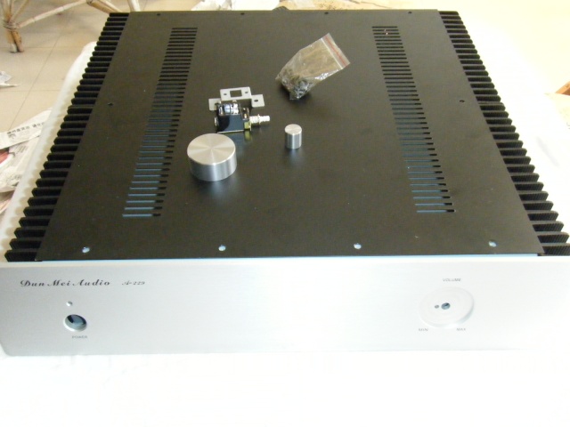
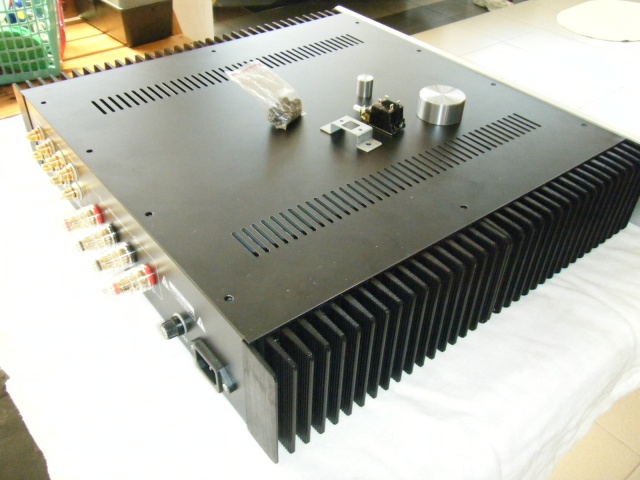
This is a chassis imported from China and sold by Kakibook from Kuala Lumpur. The front plate and heat sinks are made of aluminum and the rest of the body is from mild steel. All the holes are pre-drilled and the chassis accessories are supplied to as a whole package. Although the heat sinks are not used, it looks pretty nice with the hybrid amplifier.
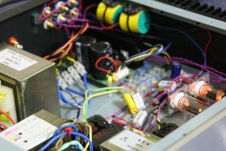
This is a side view of the internal when the hybrid amplifier is powered on. I simply love the 5687 and EZ81 glow. Perhaps I should open a hole on the top panel and display both tubes externally. Due to safety reason, it was kept internally to prevent itchy hands or paws.
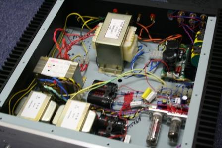
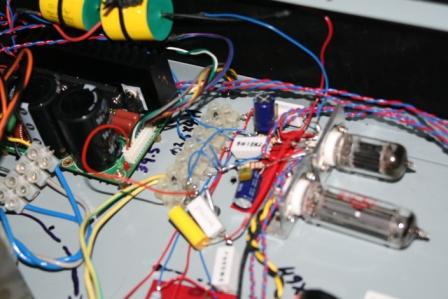
This is a top view of the internal of the hybrid amplifier. It houses 2 power transformers, one for the 5687 preamplifier section, one for the TA2022 class T amplifier section. There are 2 chokes on the bottom left. All the B+ uses the capacitors from JJ-electronic. The coupling between the preamp and power amp is 4.7uF Auricaps. The vacuum tubes are mounted horizontally with a very study 3mm thick L-shape aluminum plate. I did not splash that much on the components as this is a prototype that’s going to be send to a friend for evaluation. The wires are not trimmed to keep the reusability when it is ready to house in a proper chassis. This amplifier can act as a hybrid integrated amplifier, a 5687 tube preamplifier, as well as TA2022 power amplifier.
This is a closer look at the tube preamplifier section of the hybrid amplifier – JJ EZ81 and Tungsol 5687WA vacuum tube. The sound? I leave it for you to discover it yourself. The internet has thousands of articles written on Tripath amplifier – it is that good, and it is even better with the 5687 tube preamplifier thrown into the recipe. Return from DIY Amplifiers, Solid State / Hybrid Amplifier to DIY Audio Guide
|
